Network Architecture Deep Dive: Amazon VPC CNI in EKS
The Kubernetes Container Network Interface (CNI) serves as the fundamental framework for configuring network connectivity in Kubernetes environments. While various CNI plugins are available in the ecosystem, Amazon EKS implements cluster networking through its native VPC Container Network Interface (VPC CNI) plugin.
What makes VPC CNI special is its ability to assign VPC IP addresses directly to Kubernetes pods, enabling them to operate as first-class citizens within your VPC network architecture. Within each pod, all containers share a common network namespace, facilitating seamless inter-container communication through local ports.
Core Components of Amazon VPC CNI
CNI Binary handles Pod-to-Pod communication setup. Operating from the node’s root filesystem, it springs into action whenever kubelet signals pod lifecycle events (creation or termination). The binary ensures proper network configuration for each pod, managing the intricate details of network setup and teardown.
IPAMD (IP Address Management Daemon): This node-local daemon, known as ipamd, serves as the IP address orchestrator with two primary responsibilities:
- Manages Elastic Network Interfaces (ENIs) at the node level
- Maintains a warm pool of available IP addresses or prefixes to enable rapid pod scheduling
Every EC2 instance in your EKS cluster starts with a primary ENI attached to either a public or private subnet. Pods running in hostNetwork mode utilize this primary ENI’s IP address and share the host’s network namespace.
The CNI plugin implements a sophisticated ENI management strategy:
- Automatically allocates a pool of IP/prefix slots from the subnet to the primary ENI during node provisioning
- Maintains a “warm pool” of pre-allocated resources, sized according to the instance type
- Dynamically attaches secondary ENIs as needed to maintain the warm pool
- Each ENI supports a varying number of slots based on the instance type
- Continues adding ENIs until reaching the instance’s maximum limit
The maximum pod density per node is determined by several factors:
- Instance type’s ENI limit
- Number of IP addresses supported per ENI
- Available compute resources (CPU/Memory)
Best Practices would be like:
- Exclude hostNetwork pods from pod density calculations
- Utilize the max-pod-calculator.sh script to determine optimal pod limits for your instance type
Understanding Network Namespaces in EKS
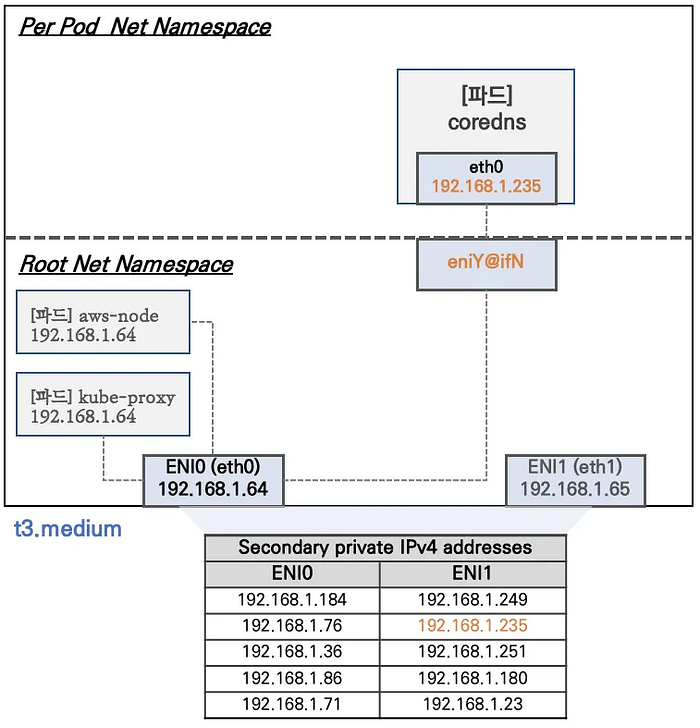
In Amazon EKS, network namespaces are segregated into two primary categories: Root Network Namespace and Per-Pod Network Namespace. This separation is crucial for maintaining network isolation and security.
Root Network Namespace:
- Houses system-critical pods that require direct host network access
- Specifically, pods like kube-proxy and aws-node operate with the Host Network option enabled
- These pods share the same IP address (192.168.1.64) as the host node
- Primary ENI (ENI0) configuration: eth0 with IP 192.168.1.64 (e.g.)
- Secondary ENI (ENI1) configuration: eth1 with IP 192.168.1.65 (e.g.)
Per-Pod Network Namespace:
- Dedicated network namespace for individual pods (like CoreDNS)
- Connected to the root namespace through virtual Ethernet (veth) pairs
- Uses eniY@ifN interface on the host side
- Each pod gets its own eth0 interface (example: 192.168.1.235 for CoreDNS)
Network Namespace Characteristics
Host Network Pods:
- Certain system pods like kube-proxy and aws-node use the host’s IP directly
- This is achieved through the Pod’s hostNetwork: true option
- These pods share the host’s network namespace
ENI IP Allocation:
- For t3.medium instances, each ENI can support up to 6 IP addresses
- Primary ENI (ENI0) and Secondary ENI (ENI1) each get:
- One primary IP
- Up to 5 secondary private IPs
Pod Networking:
- CoreDNS pods use virtual ethernet (veth) pairs
- Host side: eniY@ifN interface
- Pod side: eth0 interface
First, let’s examine the CoreDNS pod IP assignments:
# Check CoreDNS pod IP information
kubectl get pod -n kube-system -l k8s-app=kube-dns -owide

# Examine node routing tables
for i in $N1 $N2 $N3; do
    echo "=== Node: $i ==="
    ssh ec2-user@$i sudo ip -c route
    echo
done
Set up monitoring terminals:
# Terminal 1 - Monitor Node 1
ssh ec2-user@$N1
watch -d "ip link | egrep 'eth|eni' ;echo;echo '[ROUTE TABLE]'; route -n | grep eni"

# Terminal 2 - Monitor Node 2
ssh ec2-user@$N2
watch -d "ip link | egrep 'eth|eni' ;echo;echo '[ROUTE TABLE]'; route -n | grep eni"

# Terminal 3 - Monitor Node 3
ssh ec2-user@$N3
watch -d "ip link | egrep 'eth|eni' ;echo;echo '[ROUTE TABLE]'; route -n | grep eni"
Deploy test pods:
# Create test deployment
cat <<EOF | kubectl apply -f -
apiVersion: apps/v1
kind: Deployment
metadata:
  name: netshoot-pod
spec:
  replicas: 3
  selector:
    matchLabels:
      app: netshoot-pod
  template:
    metadata:
      labels:
        app: netshoot-pod
    spec:
      containers:
      - name: netshoot-pod
        image: nicolaka/netshoot
        command: ["tail"]
        args: ["-f", "/dev/null"]
      terminationGracePeriodSeconds: 0
EOF

# Store pod names for easy reference
PODNAME1=$(kubectl get pod -l app=netshoot-pod -o jsonpath={.items[0].metadata.name})
PODNAME2=$(kubectl get pod -l app=netshoot-pod -o jsonpath={.items[1].metadata.name})
PODNAME3=$(kubectl get pod -l app=netshoot-pod -o jsonpath={.items[2].metadata.name})
When pods are created, the worker nodes are configured with new ENI interfaces and routing table entries. Let’s examine these changes.
# Connect to Node 3 for detailed inspection
ssh ec2-user@$N3

# Check interface information
ip -br -c addr show
ip -c link
ip -c addr
ip route

# Examine network namespaces
sudo lsns -o PID,COMMAND -t net | awk 'NR>2 {print $1}' | tail -n 1

# Check pod network namespace configuration
MyPID=$(sudo lsns -o PID,COMMAND -t net | awk 'NR>2 {print $1}' | tail -n 1)
sudo nsenter -t $MyPID -n ip -c addr
sudo nsenter -t $MyPID -n ip -c route
To enable following points for the configuration of direct pod-to-pod communication with eifficient network isloation…
Network Interface Configuration:
- Each node has multiple ENIs attached
- ENIs are configured with multiple IP addresses
- Virtual ethernet pairs connect pods to the host network
Routing Configuration:
- Pod IPs are routed through specific ENI interfaces
- Each pod gets its own routing table entries
- Secondary IP addresses are used for pod networking
Network Namespace Separation:
- System pods use host networking
- Application pods get their own network namespaces
- Each namespace has its own network stack
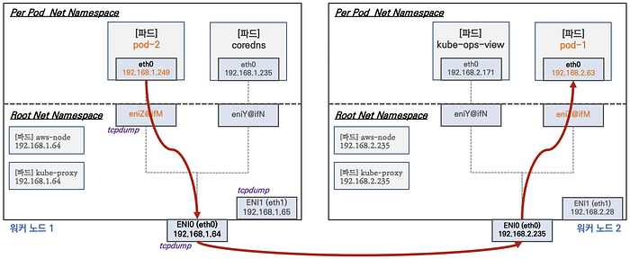
Inter-Pod Communication in EKS
A key advantage of AWS VPC CNI is its ability to enable direct pod-to-pod communication without requiring overlay networking.
Testing Pod-to-Pod Communication
First, let’s capture pod IP addresses for our tests:
# Store pod IPs in variables
PODIP1=$(kubectl get pod -l app=netshoot-pod -o jsonpath={.items[0].status.podIP})
PODIP2=$(kubectl get pod -l app=netshoot-pod -o jsonpath={.items[1].status.podIP})
PODIP3=$(kubectl get pod -l app=netshoot-pod -o jsonpath={.items[2].status.podIP})

# Verify connectivityebetween pods
echo "Testing connectivity between pods..."
echo "Pod 1 ($PODIP1) to Pod 2 ($PODIP2):"
kubectl exec -it $PODNAME1 -- ping -c 2 $PODIP2

echo -e "\nPod 2 ($PODIP2) to Pod 3 ($PODIP3):"
kubectl exec -it $PODNAME2 -- ping -c 2 $PODIP3

echo -e "\nPod 3 ($PODIP3) to Pod 1 ($PODIP1):"
kubectl exec -it $PODNAME3 -- ping -c 2 $PODIP1
To understand the traffic flow, we can monitor packets on various interfaces:
# On worker node, monitor ICMP traffic across interfaces
sudo tcpdump -i any -nn icmp       # All interfaces
sudo tcpdump -i eth1 -nn icmp      # Secondary ENI
sudo tcpdump -i eth0 -nn icmp      # Primary ENI
sudo tcpdump -i eni* -nn icmp      # Specific ENI interface
On the worker node, inspect the routing setup.
# Check routing policy database
ip rule
# Sample output shows multiple routing tables:
# 0: from all lookup local
# 512: from all to 192.168.3.240 lookup main
# 512: from all to 192.168.3.251 lookup main
# 1024: from all fwmark 0x80/0x80 lookup main
# 32766: from all lookup main
# 32767: from all lookup default

# Examine local routing table
ip route show table local
# Shows detailed local route entries including:
# broadcast 127.0.0.0 dev lo proto kernel scope link src 127.0.0.1
# local 127.0.0.0/8 dev lo proto kernel scope host src 127.0.0.1
# broadcast 127.255.255.255 dev lo proto kernel scope link

# Check main routing table
ip route show table main
# Default route configuration:
# default via 192.168.1.1 dev eth0
# 192.168.3.0/24 dev eth0 proto kernel scope link src 192.168.3.121
External Pod Communication in EKS
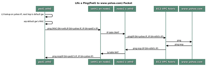
The communication flow from pods to external networks is handled through Source Network Address Translation (SNAT) using the node’s eth0 IP address. Let’s explore this in detail with practical demonstrations.
# Test external connectivity from pod-1
echo "Testing external connectivity from pod-1..."
kubectl exec -it $PODNAME1 -- ping -c 1 www.google.com
# Test with shorter interval for continuous monitoring
kubectl exec -it $PODNAME1 -- ping -i 0.1 www.google.com
On the worker node, observe the ICMP traffic:
# Monitor all interfaces for ICMP traffic
sudo tcpdump -i any -nn icmp

# Focus on primary network interface
sudo tcpdump -i eth0 -nn icmp
Let’s examine the public IP addresses:
# Check public IPs of worker nodes
for node in $N1 $N2 $N3; do
  echo "=== Public IP of node: $node ==="
  ssh ec2-user@$node "curl -s ipinfo.io/ip"
  echo
done

# Check public IP as seen by pods
for pod in $PODNAME1 $PODNAME2 $PODNAME3; do
  echo "=== Public IP as seen from pod: $pod ==="
  kubectl exec -it $pod -- curl -s ipinfo.io/ip
  echo
done
Let’s test external connectivity with a weather service:
# Get weather information for Seoul
kubectl exec -it $PODNAME1 -- curl -s wttr.in/seoul?format=3

# Get detailed weather report
kubectl exec -it $PODNAME1 -- curl -s wttr.in/seoul

# Check moon phase
kubectl exec -it $PODNAME1 -- curl -s wttr.in/Moon

# View available options
kubectl exec -it $PODNAME1 -- curl -s wttr.in/:help
On the worker node, examine the routing and NAT rules:
# Check routing policies
ip rule

# Examine main routing table
ip route show table main

# View NAT rules
sudo iptables -L -n -v -t nat
sudo iptables -t nat -S

# Focus on AWS SNAT chain rules
sudo iptables -t nat -S | grep 'A AWS-SNAT-CHAIN'
Key SNAT Rules Analysis:
# Rule 1: Return if destination is within VPC
-A AWS-SNAT-CHAIN-0 ! -d 192.168.0.0/16 -m comment --comment "AWS SNAT CHAIN" -j RETURN

# Rule 2: Perform SNAT for external traffic
-A AWS-SNAT-CHAIN-0 ! -o vlan+ -m comment --comment "AWS, SNAT" -m addrtype ! --dst-type LOCAL -j SNAT --to-source 192.168.1.251 --random-fully
Kubernetes Post-routing Rules:
# These rules handle kubernetes service traffic
-A KUBE-POSTROUTING -m mark ! --mark 0x4000/0x4000 -j RETURN
-A KUBE-POSTROUTING -j MARK --set-xmark 0x4000/0x0
-A KUBE-POSTROUTING -m comment --comment "kubernetes service traffic requiring SNAT" -j MASQUERADE --random-fully
Monitoring NAT Rule Usage:
# Reset counters
sudo iptables -t filter --zero
sudo iptables -t nat --zero
sudo iptables -t mangle --zero
sudo iptables -t raw --zero

# Watch NAT chain statistics
watch -d 'sudo iptables -v --numeric --table nat --list AWS-SNAT-CHAIN-0;
         echo;
         sudo iptables -v --numeric --table nat --list KUBE-POSTROUTING;
         echo;
         sudo iptables -v --numeric --table nat --list POSTROUTING'
Connection Tracking Analysis:
# Monitor active connections across nodes
for node in $N1 $N2 $N3; do
  echo "=== Connections on node: $node ==="
  ssh ec2-user@$node "sudo conntrack -L -n | grep -v '169.254.169'"
  echo
done
From the above, we can conclude the following.
- The iptables rules showing the SNAT configuration that enables external communication
- Active connection tracking entries showing both ICMP and TCP connections with proper NAT translations
- Pods can access external services while maintaining proper source address translation
- Return traffic is correctly routed back to the originating pods
- Connection state is properly tracked for stateful connections
- Traffic within the VPC subnet (192.168.0.0/16) bypasses SNAT
- External traffic is properly translated using the node’s IP address
Pod Density Limits in Amazon EKS
First, let’s install kube-ops-view for visual monitoring:
# Add Helm repository
helm repo add geek-cookbook https://geek-cookbook.github.io/charts/

# Install kube-ops-view with LoadBalancer service
helm install kube-ops-view geek-cookbook/kube-ops-view \
  --version 1.2.2 \
  --set service.main.type=LoadBalancer \
  --set env.TZ="Asia/Seoul" \
  --namespace kube-system

# Get the access URL (1.5x scale)
kubectl get svc -n kube-system kube-ops-view \
  -o jsonpath={.status.loadBalancer.ingress[0].hostname} | \
  awk '{ print "KUBE-OPS-VIEW URL = http://"$1":8080/#scale=1.5"}'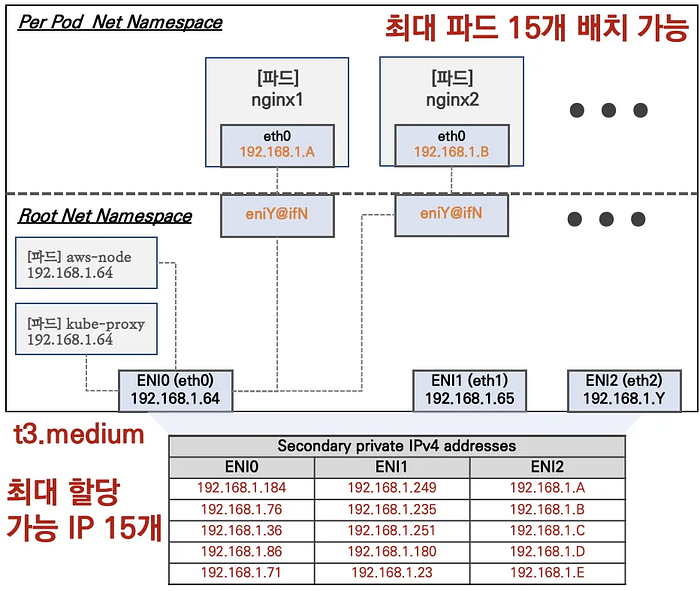
The maximum number of pods per node is determined by the formula:
Max Pods = (Number of ENIs × (IPs per ENI - 1)) + 2- Each instance type has different ENI and IP address limits
- aws-node and kube-proxy pods use host networking and don’t count towards IP limits
- Secondary IPv4 addresses are allocated based on instance type capabilities
Set up monitoring terminals:
# Terminal 1 - Monitor node network interfaces
ssh ec2-user@$NODE "while true; do
  ip -br -c addr show
  echo '--------------'
  date '+%Y-%m-%d %H:%M:%S'
  sleep 1
done"

# Terminal 2 - Watch pod distribution
watch -d 'kubectl get pods -o wide'
Create and scale a test deployment:
# Download and apply deployment manifest
curl -s -O https://raw.githubusercontent.com/gasida/PKOS/main/2/nginx-dp.yaml
kubectl apply -f nginx-dp.yaml

# Verify initial pod creation
kubectl get pod -o wide
kubectl get pod -o=custom-columns=NAME:.metadata.name,IP:.status.podIP

# Test various pod density scenarios
echo "Testing pod scaling scenarios..."

# Scenario 1: Moderate scale (8 pods)
kubectl scale deployment nginx-deployment --replicas=8
echo "Waiting for pods to stabilize..."
sleep 30

# Scenario 2: Increased load (15 pods)
kubectl scale deployment nginx-deployment --replicas=15
echo "Waiting for pods to stabilize..."
sleep 30

# Scenario 3: High density (30 pods)
kubectl scale deployment nginx-deployment --replicas=30
echo "Waiting for pods to stabilize..."
sleep 30

# Scenario 4: Maximum capacity test (50 pods)
kubectl scale deployment nginx-deployment --replicas=50
echo "Waiting for pods to stabilize..."
sleep 30
When we hit the pod density limit:
# Check pending pods
kubectl get pods | grep Pending

# Analyze scheduling failures
for pod in $(kubectl get pods | grep Pending | cut -d' ' -f1); do
  echo "=== Analyzing pod: $pod ==="
  kubectl describe pod $pod | grep -A5 "Events:"
done
The following is the stage of observation results.
- Initial Scaling (8 pods):
- Pods distribute evenly across nodes
- ENI and IP allocation remains stable
2. Medium Scale (15 pods):
- Additional ENIs may be provisioned
- IP addresses allocated from existing ENIs
3. High Density (30 pods):
- Approaches instance type limits
- May see slower pod scheduling
4. Maximum Capacity Test (50 pods):
- Pods enter Pending state
- Scheduler error: “Too many pods”
- Error message indicates both node capacity and preemption limitations
From this meaning, understanding these limits is crucial for 1) proper cluster capacity planning, 2) instance type selection, 3) pod distribution strategies, and 4) High availability considerations.
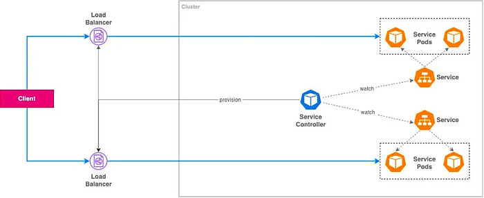
Service & AWS LoadBalancer Controller
- ClusterIP Type
- Provides internal cluster access only
- Stable internal IP address
- Default service type
- Only accessible within the cluster
# Example ClusterIP Service
apiVersion: v1
kind: Service
metadata:
  name: my-internal-service
spec:
  type: ClusterIP
  selector:
    app: my-app
  ports:
    - port: 80
      targetPort: 8080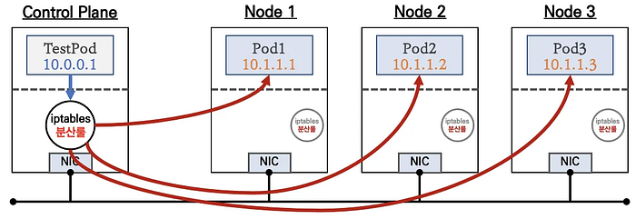
2. NodePort Type
- Exposes service on each node’s IP at a static port
- Accessible from outside the cluster
- Automatically creates ClusterIP service
apiVersion: v1
kind: Service
metadata:
  name: my-nodeport-service
spec:
  type: NodePort
  selector:
    app: my-app
  ports:
    - port: 80
      targetPort: 8080
      nodePort: 30080  # Port range: 30000-32767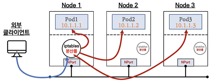
3. LoadBalancer Type (the default mode for NLB instances)
Traffic Flow:
- External traffic → NLB
- NLB → Node (Instance targets)
- Node iptables → Pod
- Double NAT process
- Client IP not preserved in default mode
apiVersion: v1
kind: Service
metadata:
  name: my-nlb-instance-service
spec:
  type: LoadBalancer
  externalTrafficPolicy: Cluster  # Default mode
  selector:
    app: my-app
  ports:
    - port: 80
      targetPort: 8080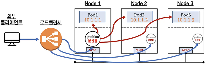
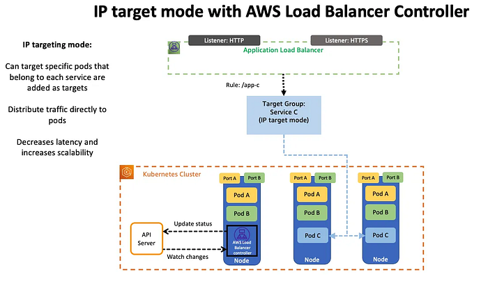
4. LoadBalancer Controller Service Type (NLP IP mode with VPC CNI)
apiVersion: v1
kind: Service
metadata:
  name: my-nlb-ip-service
  annotations:
    service.beta.kubernetes.io/aws-load-balancer-type: "nlb-ip"
    service.beta.kubernetes.io/aws-load-balancer-nlb-target-type: "ip"
spec:
  type: LoadBalancer
  externalTrafficPolicy: Local
  ports:
    - port: 80
      targetPort: 8080
  selector:
    app: my-app
5. External Traffic Policy Configurations

A. Cluster Mode (Default):
apiVersion: v1
kind: Service
metadata:
  name: example-service
spec:
  type: LoadBalancer  # Creates NLB in instance mode
  externalTrafficPolicy: Cluster  # Default setting
  ports:
    - port: 80
      targetPort: 8080
  selector:
app: example- NLB targets worker nodes (instances)
Double NAT process occurs:
- First DNAT: Load balancer to node
- Second DNAT: Node’s iptables to pod
- Client IP is not preserved in default mode
B. Local Mode:
apiVersion: v1
kind: Service
metadata:
  name: example-local-service
spec:
  type: LoadBalancer
  externalTrafficPolicy: Local  # Enables direct node routing
  ports:
    - port: 80
      targetPort: 8080
  selector:
app: example- Single hop traffic distribution
- Preserves client IP address
- Uses node iptables for local pod routing
- Health checks ensure traffic only routes to nodes with active pods
C. NLB IP Mode with Proxy Protocol v2 (without proxy protocol)
apiVersion: v1
kind: Service
metadata:
  name: example-ip-mode
  annotations:
    service.beta.kubernetes.io/aws-load-balancer-type: "nlb-ip"
    service.beta.kubernetes.io/aws-load-balancer-nlb-target-type: "ip"
spec:
  type: LoadBalancer
  ports:
    - port: 80
      targetPort: 8080
  selector:
app: example- Direct pod routing
- Client IP is NATted by NLB
D. NLB IP Mode with Proxy Protocol v2 (with proxy protocol v2)
metadata:
  annotations:
    service.beta.kubernetes.io/aws-load-balancer-type: "nlb-ip"
service.beta.kubernetes.io/aws-load-balancer-proxy-protocol: "*"- Direct pod routing
- Preserves client IP
- Requires application support for Proxy Protocol
E. Load Balancing Optimization
metadata:
  annotations:
    service.beta.kubernetes.io/aws-load-balancer-healthcheck-protocol: "HTTP"
    service.beta.kubernetes.io/aws-load-balancer-healthcheck-path: "/health"
service.beta.kubernetes.io/aws-load-balancer-healthcheck-port: "8080"- Only nodes with healthy pods receive traffic
- Failed health checks remove nodes from target group
- Prevents unnecessary routing
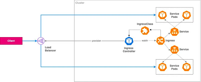
Ingress
Ingress serves as a web proxy that exposes cluster-internal services (ClusterIP, NodePort, LoadBalancer) to external traffic via HTTP/HTTPS.
# Basic Ingress Configuration Example
apiVersion: networking.k8s.io/v1
kind: Ingress
metadata:
  name: example-ingress
  annotations:
    alb.ingress.kubernetes.io/scheme: internet-facing
    alb.ingress.kubernetes.io/target-type: ip
spec:
  ingressClassName: alb
  rules:
    - host: app.example.com
      http:
        paths:
          - path: /
            pathType: Prefix
            backend:
              service:
                name: app-service
                port:
number: 80A. Service Exposure (In-tree Service Controller):
apiVersion: v1
kind: Service
metadata:
  name: example-service
spec:
  type: LoadBalancer
  ports:
    - port: 80
      targetPort: 8080
  selector:
    app: example
B. External Load Balancer Implementation:
apiVersion: networking.k8s.io/v1
kind: Ingress
metadata:
name: alb-ingress
annotations:
kubernetes.io/ingress.class: alb
alb.ingress.kubernetes.io/scheme: internet-facing
spec:
rules:
- http:
paths:
- path: /*
backend:
service:
name: example-service
port:
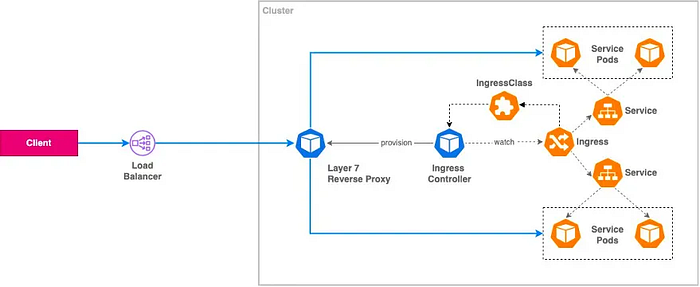
number: 80C. Internal Reverse Proxy:
apiVersion: networking.k8s.io/v1
kind: Ingress
metadata:
  name: nginx-ingress
  annotations:
    nginx.ingress.kubernetes.io/rewrite-target: /
spec:
  ingressClassName: nginx
  rules:
    - host: internal.example.com
      http:
        paths:
          - path: /app
            pathType: Prefix
            backend:
              service:
                name: internal-service
                port:
                  number: 80
D. Kubernetes Gateway API
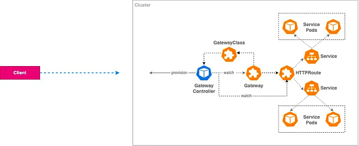
ExternalDNS Setup with Route 53
ExternalDNS automatically synchronizes exposed Kubernetes Services and Ingresses with DNS providers by…
- Creating DNS records automatically when Services/Ingresses are created
- Removing DNS records when Services/Ingresses are deleted
- Supporting multiple DNS providers (AWS Route53, Azure DNS, Google Cloud DNS)

To do this, setup the required variables at first.
# Set domain variable
MyDomain="example.com"
echo "export MyDomain=${MyDomain}" >> /etc/profile

# Get Route 53 Hosted Zone ID
MyDnzHostedZoneId=$(aws route53 list-hosted-zones-by-name \
  --dns-name "${MyDomain}." \
  --query "HostedZones[0].Id" \
  --output text)
echo "Hosted Zone ID: ${MyDnzHostedZoneId}"
ExternalDNS Controller Configuration:
apiVersion: apps/v1
kind: Deployment
metadata:
  name: external-dns
  namespace: kube-system
spec:
  strategy:
    type: Recreate
  selector:
    matchLabels:
      app: external-dns
  template:
    metadata:
      labels:
        app: external-dns
    spec:
      serviceAccountName: external-dns
      containers:
        - name: external-dns
          image: registry.k8s.io/external-dns/external-dns:v0.13.5
          args:
            - --source=service
            - --source=ingress
            - --domain-filter=${MyDomain}
            - --provider=aws
            - --aws-zone-type=public
            - --registry=txt
            - --txt-owner-id=${MyDnzHostedZoneId}
Monitor DNS Records:
# List all A records
aws route53 list-resource-record-sets \
  --hosted-zone-id "${MyDnzHostedZoneId}" \
  --query "ResourceRecordSets[?Type == 'A']" | jq

# Continuous monitoring of A records
while true; do
  aws route53 list-resource-record-sets \
    --hosted-zone-id "${MyDnzHostedZoneId}" \
    --query "ResourceRecordSets[?Type == 'A']" | jq
  echo "Last checked: $(date)"
  sleep 1
done
Verify NS Records:
# List NS records
aws route53 list-resource-record-sets \
  --output json \
  --hosted-zone-id "${MyDnzHostedZoneId}" \
  --query "ResourceRecordSets[?Type == 'NS']" | \
  jq -r '.[0].ResourceRecords[].Value'
Authentication Methods
- Node IAM Role
- IRSA (IAM Roles for Service Accounts)
# Add Route 53 permissions to node role
aws iam attach-role-policy \
  --role-name ${NODE_ROLE_NAME} \
  --policy-arn arn:aws:iam::aws:policy/AmazonRoute53FullAccess

apiVersion: v1
kind: ServiceAccount
metadata:
  name: external-dns
  namespace: kube-system
  annotations:
    eks.amazonaws.com/role-arn: arn:aws:iam::ACCOUNT_ID:role/external-dns-role
ExternalDNS Deployment…
apiVersion: apps/v1
kind: Deployment
metadata:
  name: external-dns
  namespace: kube-system
spec:
  strategy:
    type: Recreate
  selector:
    matchLabels:
      app: external-dns
  template:
    metadata:
      labels:
        app: external-dns
    spec:
      serviceAccountName: external-dns
      containers:
      - name: external-dns
        image: registry.k8s.io/external-dns/external-dns:v0.13.5
        args:
        - --source=service
        - --source=ingress
        - --provider=aws
        - --policy=upsert-only
        - --registry=txt
        - --txt-owner-id=external-dns
        env:
        - name: AWS_REGION
          value: ${AWS_REGION}
Service/Ingress Example with DNS Integration:
apiVersion: v1
kind: Service
metadata:
  name: my-service
  annotations:
    external-dns.alpha.kubernetes.io/hostname: app.example.com
spec:
  type: LoadBalancer
  ports:
  - port: 80
    targetPort: 8080
---
apiVersion: networking.k8s.io/v1
kind: Ingress
metadata:
  name: my-ingress
  annotations:
    external-dns.alpha.kubernetes.io/hostname: web.example.com
spec:
  rules:
  - host: web.example.com
    http:
      paths:
      - path: /
        pathType: Prefix
        backend:
          service:
            name: my-service
            port:
              number: 80
Verification and Monitoring…
# Monitor DNS record creation
kubectl logs -f deployment/external-dns -n kube-system

# Verify Route53 records
aws route53 list-resource-record-sets \
    --hosted-zone-id ${HOSTED_ZONE_ID} \
    --query "ResourceRecordSets[?Type=='A']"
CoreDNS in Kubernetes
DNS resolution in Kubernetes follows a specific path that ensures efficient and reliable name resolution. The flow proceeds as follows:
- Application in Pod initiates a DNS query
- Query is processed by the Pod’s DNS resolver
- Request is forwarded to CoreDNS through the cluster’s DNS service IP
- CoreDNS processes the request using:
- Kubernetes API for service/pod lookups
- Internal cache for recently resolved queries
- External DNS servers for external domain resolution
- Response follows the reverse path back to the application

CoreDNS runs as a deployment in the kube-system namespace. Here’s a detailed look at its configuration.
apiVersion: v1
kind: Pod
metadata:
  name: coredns
  namespace: kube-system
spec:
  containers:
  - name: coredns
    image: coredns/coredns:1.9.3
    args: ["-conf", "/etc/coredns/Corefile"]
    volumeMounts:
    - name: config-volume
      mountPath: /etc/coredns
      readOnly: true
    ports:
    - containerPort: 53
      name: dns
      protocol: UDP
    - containerPort: 53
      name: dns-tcp
      protocol: TCP
    - containerPort: 9153
      name: metrics
      protocol: TCP
    livenessProbe:
      httpGet:
        path: /health
        port: 8080
        scheme: HTTP
    readinessProbe:
      httpGet:
        path: /ready
        port: 8181
        scheme: HTTP
CoreDNS Configuration (Corefile) looks like the following.
apiVersion: v1
kind: ConfigMap
metadata:
  name: coredns
  namespace: kube-system
data:
  Corefile: |
    .:53 {
        # Error logging
        errors {
            consolidate 5m
        }

        # Health checking
        health {
            lameduck 5s
        }

        # Kubernetes DNS integration
        kubernetes cluster.local in-addr.arpa ip6.arpa {
            pods insecure
            fallthrough in-addr.arpa ip6.arpa
            ttl 30
        }

        # Prometheus metrics
        prometheus :9153

        # Forward external queries
        forward . /etc/resolv.conf {
            max_concurrent 1000
            prefer_udp
        }

        # Caching
        cache {
            success 10000
            denial 1000
            prefetch 10
            serve_stale
        }

        # Loop detection
        loop

        # Auto-reload configuration
        reload

        # Load balancing
        loadbalance round_robin
    }
Service Discovery:
# ClusterIP Service DNS Format
# <service-name>.<namespace>.svc.cluster.local

# Test internal service resolution
kubectl run dns-test --rm -i --tty --image=nicolaka/netshoot -- dig svc-example.default.svc.cluster.local

# Example output:
;; ANSWER SECTION:
svc-example.default.svc.cluster.local. 30 IN A 10.100.71.123
Pod DNS Resolution:
# Pod DNS Format
# <pod-ip>.<namespace>.pod.cluster.local

# Convert Pod IP 10.244.2.7 to DNS format
kubectl run dns-test --rm -i --tty --image=nicolaka/netshoot -- dig 10-244-2-7.default.pod.cluster.local

# Example output:
;; ANSWER SECTION:
10-244-2-7.default.pod.cluster.local. 30 IN A 10.244.2.7
CoreDNS Status Check:
# Check CoreDNS pods
kubectl get pods -n kube-system -l k8s-app=kube-dns -o wide

# View CoreDNS logs
kubectl logs -n kube-system -l k8s-app=kube-dns

# Check CoreDNS metrics
kubectl port-forward -n kube-system deploy/coredns 9153:9153
curl localhost:9153/metrics
DNS Resolution Testing:
# Create debugging pod
cat <<EOF | kubectl apply -f -
apiVersion: v1
kind: Pod
metadata:
  name: dnsutils
spec:
  containers:
  - name: dnsutils
    image: gcr.io/kubernetes-e2e-test-images/dnsutils:1.3
    command: ["sleep", "infinity"]
EOF

# Run DNS tests
kubectl exec -it dnsutils -- bash -c '
echo "=== Testing internal service DNS ==="
nslookup kubernetes.default.svc.cluster.local

echo -e "\n=== Testing pod DNS ==="
nslookup 10-244-2-7.default.pod.cluster.local

echo -e "\n=== Testing external DNS ==="
nslookup kubernetes.io

echo -e "\n=== DNS Configuration ==="
cat /etc/resolv.conf
'
Custom DNS Records:
# Add custom DNS entries
apiVersion: v1
kind: ConfigMap
metadata:
  name: coredns-custom
  namespace: kube-system
data:
  custom.server: |
    example.local:53 {
        hosts {
            10.0.0.1 custom.example.local
            fallthrough
        }
    }
DNS Policies:
# Pod with custom DNS policy
apiVersion: v1
kind: Pod
metadata:
  name: custom-dns-pod
spec:
  dnsPolicy: "None"
  dnsConfig:
    nameservers:
      - 8.8.8.8
    searches:
      - custom.svc.cluster.local
    options:
      - name: ndots
        value: "5"
  containers:
    - name: dns-example
      image: nginx
Topology Aware Routing
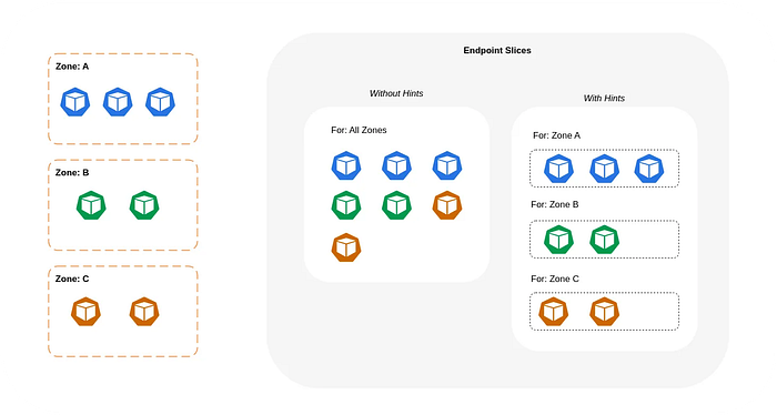
Topology Aware Routing is a mechanism that enables network traffic to stay within its originating zone in Kubernetes clusters.
- Reduced cross-zone data transfer costs
- Lower latency by avoiding cross-zone communication
- Improved application reliability
- Better network performance and throughput
- Enhanced failure isolation
First, let’s verify our multi-zone cluster configuration:
# Check availability zone distribution
echo "Checking node distribution across zones..."
kubectl get node --label-columns=topology.kubernetes.io/zone
We’ll deploy an application that’s topology-aware using the following configuration. The service configuration is crucial for enabling topology-aware routing.
# First, deploy a multi-zone test application
apiVersion: apps/v1
kind: Deployment
metadata:
  name: deploy-echo
  annotations:
    kubernetes.io/description: "Multi-zone echo server deployment for topology testing"
spec:
  replicas: 3  # One replica per zone for testing
  selector:
    matchLabels:
      app: deploy-websrv
  template:
    metadata:
      labels:
        app: deploy-websrv
    spec:
      topologySpreadConstraints:  # Ensure pods spread across zones
      - maxSkew: 1
        topologyKey: topology.kubernetes.io/zone
        whenUnsatisfiable: ScheduleAnyway
        labelSelector:
          matchLabels:
            app: deploy-websrv
      containers:
      - name: websrv
        image: registry.k8s.io/echoserver:1.5
        ports:
        - name: http
          containerPort: 8080
        readinessProbe:
          httpGet:
            path: /
            port: 8080
          initialDelaySeconds: 5
          periodSeconds: 10
        livenessProbe:
          httpGet:
            path: /
            port: 8080
          initialDelaySeconds: 15
          periodSeconds: 20
---
# Service with Topology Aware Routing enabled
apiVersion: v1
kind: Service
metadata:
  name: svc-clusterip
  annotations:
    service.kubernetes.io/topology-mode: "auto"
    kubernetes.io/description: "Topology-aware service for zone-local routing"
spec:
  ports:
    - name: svc-webport
      port: 80
      targetPort: 8080
      protocol: TCP
  selector:
    app: deploy-websrv
  type: ClusterIP
Deploy test clients in each zone and verify routing behavior:
# Check zone distribution of nodes
echo "=== Checking Node Zone Distribution ==="
kubectl get node --label-columns=topology.kubernetes.io/zone

# Deploy test client pods in each zone
for zone in $(kubectl get nodes -L topology.kubernetes.io/zone --no-headers | awk '{print $6}' | sort -u); do
  cat <<EOF | kubectl apply -f -
apiVersion: v1
kind: Pod
metadata:
  name: netshoot-${zone}
  labels:
    app: netshoot
spec:
  containers:
  - name: netshoot
    image: nicolaka/netshoot
    command: ["tail"]
    args: ["-f", "/dev/null"]
  nodeSelector:
    topology.kubernetes.io/zone: ${zone}
  terminationGracePeriodSeconds: 0
EOF
done

# Comprehensive testing function
test_topology_routing() {
  local pod_name=$1
  local iterations=$2

  echo "=== Testing from pod: ${pod_name} ==="
  echo "Pod Zone: $(kubectl get pod ${pod_name} -o jsonpath='{.spec.nodeSelector.topology\.kubernetes\.io/zone}')"

  # Run test requests
  echo "Performing ${iterations} test requests..."
  kubectl exec -it ${pod_name} -- zsh -c "for i in {1..${iterations}}; do
    echo -n \"Request \$i: \";
    curl -s svc-clusterip | grep Hostname;
    sleep 0.1;
  done | tee /tmp/results"

  # Analyze results
  echo -e "\nRequest Distribution:"
  kubectl exec -it ${pod_name} -- zsh -c "cat /tmp/results | sort | uniq -c | sort -nr"

  # Get target pod zones
  echo -e "\nTarget Pod Zone Distribution:"
  kubectl exec -it ${pod_name} -- zsh -c "cat /tmp/results" | while read line; do
    pod_name=$(echo $line | awk '{print $2}')
    zone=$(kubectl get pod ${pod_name} -o jsonpath='{.spec.nodeName}' | \
           xargs kubectl get node -o jsonpath='{.metadata.labels.topology\.kubernetes\.io/zone}')
    echo "${line} -> Zone: ${zone}"
  done
}

# Test from each zone
for pod in $(kubectl get pods -l app=netshoot -o name); do
  pod_name=$(echo $pod | cut -d/ -f2)
  test_topology_routing ${pod_name} 50
  echo -e "\n"
done
Monitor the EndpointSlice configuration which contains topology hints.
# Monitor EndpointSlice changes
kubectl get endpointslices -l kubernetes.io/service-name=svc-clusterip -o yaml | \
grep -A 5 "hints:"

# Watch EndpointSlice updates in real-time
kubectl get endpointslices --watch -l kubernetes.io/service-name=svc-clusterip
We implement comprehensive testing to verify topology-aware behavior.
# Monitor cross-zone traffic (requires prometheus)
cat <<EOF | kubectl apply -f -
apiVersion: monitoring.coreos.com/v1
kind: ServiceMonitor
metadata:
  name: topology-monitor
spec:
  selector:
    matchLabels:
      app: deploy-websrv
  endpoints:
  - port: http
EOF

# Custom metrics for zone awareness
cat <<EOF | kubectl apply -f -
apiVersion: v1
kind: ConfigMap
metadata:
  name: topology-metrics
data:
  recording.rules: |
    groups:
    - name: topology.rules
      rules:
      - record: topology:request:zone_distribution
        expr: |
          sum(rate(http_requests_total{service="svc-clusterip"}[5m])) by (source_zone, destination_zone)
EOF
Implement failure scenario testing to verify resilience.
# Test zone failure scenario
simulate_zone_failure() {
local zone=$1
echo "Simulating failure in zone: ${zone}"
# Cordon nodes in the zone
kubectl get nodes -l topology.kubernetes.io/zone=${zone} -o name | \
while read node; do
kubectl cordon ${node}
done
# Check traffic redistribution
echo "Checking traffic distribution after zone failure..."
for pod in $(kubectl get pods -l app=netshoot -o name); do
pod_name=$(echo $pod | cut -d/ -f2)
test_topology_routing ${pod_name} 20
done
# Uncordon nodes
kubectl get nodes -l topology.kubernetes.io/zone=${zone} -o name | \
while read node; do
kubectl uncordon ${node}
done
}
# Test each zone
for zone in $(kubectl get nodes -L topology.kubernetes.io/zone --no-headers | awk '{print $6}' | sort -u); do
simulate_zone_failure ${zone}
echo -e "\nWaiting for system to stabilize..."
sleep 30
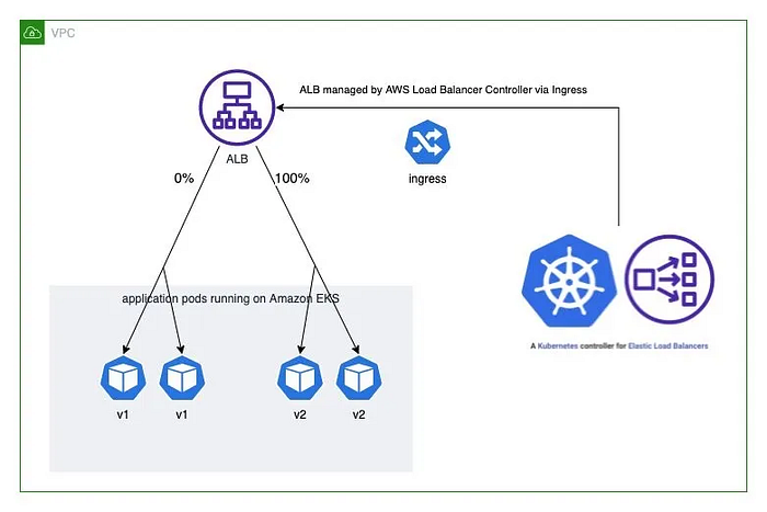
doneUsing AWS Load Balancer Controller for blue/green deployment, canary deployment and A/B testing
The AWS Load Balancer Controller enables sophisticated deployment strategies through ALB integration:
- Blue/Green Deployments: Complete traffic switching between versions
- Canary Deployments: Gradual traffic shifting
- A/B Testing: Traffic routing based on request attributes
annotations:
   ...
  alb.ingress.kubernetes.io/actions.blue-green: |
    {
      "type":"forward",
      "forwardConfig":{
        "targetGroups":[
          {
            "serviceName":"hello-kubernetes-v1",
            "servicePort":"80",
            "weight":50
          },
          {
            "serviceName":"hello-kubernetes-v2",
            "servicePort":"80",
            "weight":50
          }
        ]
      }
    }
Initial Application Deployment
# Clone sample application
git clone https://github.com/paulbouwer/hello-kubernetes.git

# Deploy Version 1
helm install --create-namespace --namespace hello-kubernetes v1 \
  ./hello-kubernetes/deploy/helm/hello-kubernetes \
  --set message="You are reaching hello-kubernetes version 1" \
  --set ingress.configured=true \
  --set service.type="ClusterIP"

# Deploy Version 2
helm install --namespace hello-kubernetes v2 \
  ./hello-kubernetes/deploy/helm/hello-kubernetes \
  --set message="You are reaching hello-kubernetes version 2" \
  --set ingress.configured=true \
  --set service.type="ClusterIP"

# Verify deployments
kubectl get pod,svc,ep -n hello-kubernetes
kubectl get pod -n hello-kubernetes \
  --label-columns=app.kubernetes.io/instance,pod-template-hash
Blue/Green deployment allows for zero-downtime updates by maintaining two identical environments and switching traffic between them.
apiVersion: networking.k8s.io/v1
kind: Ingress
metadata:
  name: "hello-kubernetes"
  namespace: "hello-kubernetes"
  annotations:
    alb.ingress.kubernetes.io/scheme: internet-facing
    alb.ingress.kubernetes.io/target-type: ip
    alb.ingress.kubernetes.io/actions.blue-green: |
      {
        "type": "forward",
        "forwardConfig": {
          "targetGroups": [
            {
              "serviceName": "hello-kubernetes-v1",
              "servicePort": "80",
              "weight": 100
            },
            {
              "serviceName": "hello-kubernetes-v2",
              "servicePort": "80",
              "weight": 0
            }
          ]
        }
      }
spec:
  ingressClassName: alb
  rules:
    - http:
        paths:
          - path: /
            pathType: Prefix
            backend:
              service:
                name: blue-green
                port:
                  name: use-annotation
Canary deployment enables gradual rollout by routing a percentage of traffic to the new version.

# Gradual traffic shift configuration
apiVersion: networking.k8s.io/v1
kind: Ingress
metadata:
  name: "hello-kubernetes"
  namespace: "hello-kubernetes"
  annotations:
    alb.ingress.kubernetes.io/actions.blue-green: |
      {
        "type": "forward",
        "forwardConfig": {
          "targetGroups": [
            {
              "serviceName": "hello-kubernetes-v1",
              "servicePort": "80",
              "weight": 90
            },
            {
              "serviceName": "hello-kubernetes-v2",
              "servicePort": "80",
              "weight": 10
            }
          ]
        }
      }
A/B testing allows routing based on request attributes like headers.
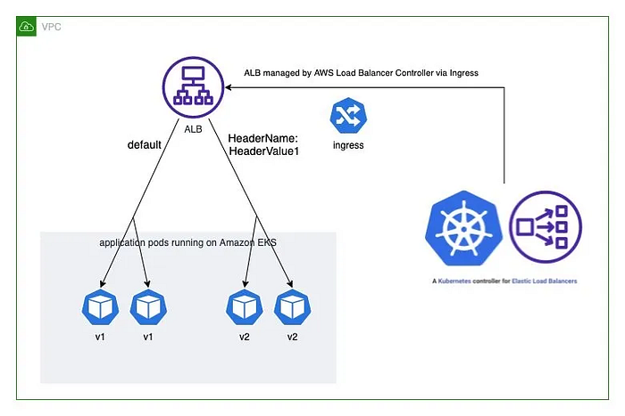
apiVersion: networking.k8s.io/v1
kind: Ingress
metadata:
  name: "hello-kubernetes"
  namespace: "hello-kubernetes"
  annotations:
    alb.ingress.kubernetes.io/conditions.ab-testing: >
      [{
        "field": "http-header",
        "httpHeaderConfig": {
          "httpHeaderName": "HeaderName",
          "values": ["kans-study-end"]
        }
      }]
    alb.ingress.kubernetes.io/actions.ab-testing: >
      {
        "type": "forward",
        "forwardConfig": {
          "targetGroups": [{
            "serviceName": "hello-kubernetes-v2",
            "servicePort": 80
          }]
        }
      }
spec:
  rules:
    - http:
        paths:
          - path: /
            pathType: Prefix
            backend:
              service:
                name: ab-testing
                port:
                  name: use-annotation
          - path: /
            pathType: Prefix
            backend:
              service:
                name: hello-kubernetes-v1
                port:
                  name: http
To ensure our deployment strategies are working as expected.
# Function to monitor traffic distribution
monitor_traffic() {
    local elb_url=$1
    local test_type=$2
    local iterations=$3
    local header=""

    if [ "$test_type" = "ab" ]; then
        header="-H 'HeaderName: kans-study-end'"
    fi

    echo "Starting traffic monitoring for $test_type deployment..."
    echo "Testing $iterations requests..."

    # Execute requests and analyze distribution
    for i in $(seq 1 $iterations); do
        if [ "$test_type" = "ab" ]; then
            curl -s -H "HeaderName: kans-study-end" $elb_url | grep version
        else
            curl -s $elb_url | grep version
        fi
        sleep 0.1
    done | sort | uniq -c | sort -nr
}

# Get ALB URL
ELB_URL=$(kubectl get ingress -n hello-kubernetes \
  -o=jsonpath='{.items[0].status.loadBalancer.ingress[0].hostname}')

# Test different deployment strategies
echo "=== Testing Blue/Green Deployment ==="
monitor_traffic $ELB_URL "blue-green" 100

echo "=== Testing Canary Deployment ==="
monitor_traffic $ELB_URL "canary" 100

echo "=== Testing A/B Testing ==="
monitor_traffic $ELB_URL "ab" 100

# Monitor ALB metrics
kubectl get events -n hello-kubernetes --sort-by='.lastTimestamp'

# Watch ingress status
kubectl get ingress -n hello-kubernetes -w

# Check target group health
aws elbv2 describe-target-health \
  --target-group-arn $(aws elbv2 describe-target-groups \
    --names $(kubectl get ingress -n hello-kubernetes \
      -o jsonpath='{.items[0].metadata.annotations.alb\.ingress\.kubernetes\.io/target-group-names}') \
    --query 'TargetGroups[0].TargetGroupArn' --output text)
Network Policies with VPC CNI
Each of these components works together to provide comprehensive network policy enforcement:
- The Network Policy Controller monitors policy changes
- The Node Agent manages eBPF program deployment
- The eBPF programs provide actual packet filtering
- The SDK enables monitoring and troubleshooting
# Verify VPC CNI configuration
kubectl get ds aws-node -n kube-system -o yaml | grep -i "enable-network-policy"
# Check Node Agent deployment
kubectl get ds aws-node -n kube-system -o yaml | grep -i image:
kubectl get pod -n kube-system -l k8s-app=aws-node
# Verify kernel version on nodes
for node in $(kubectl get nodes -o name); do
echo "Checking kernel on ${node#node/}"
ssh ec2-user@${node#node/} uname -r
done
# Verify eBPF program loading
for node in $(kubectl get nodes -o name); do
echo "=== Checking eBPF programs on ${node#node/} ==="
ssh ec2-user@${node#node/} sudo /opt/cni/bin/aws-eks-na-cli ebpf progs
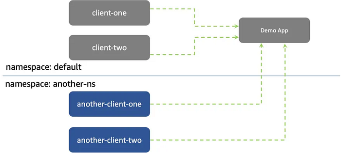
doneWe’ll deploy a test environment with multiple applications to demonstrate network policy functionality. This includes services in different namespaces to test cross-namespace communication.
# Clone the example repository
git clone https://github.com/aws-samples/eks-network-policy-examples.git
cd eks-network-policy-examples

# Deploy the sample applications
kubectl apply -f advanced/manifests/

# Verify deployments
kubectl get pod,svc
kubectl get pod,svc -n another-ns

# Test initial connectivity
echo "Testing same namespace connectivity..."
kubectl exec -it client-one -- curl demo-app

echo "Testing cross-namespace connectivity..."
kubectl exec -it another-client-one -n another-ns -- curl demo-app.default
First, we’ll implement a default deny policy to ensure all ingress traffic is blocked unless explicitly allowed.
# Create monitoring terminal
watch -n1 'kubectl exec -it client-one -- curl --connect-timeout 1 demo-app'

# Apply deny-all policy
cat <<EOF | kubectl apply -f -
apiVersion: networking.k8s.io/v1
kind: NetworkPolicy
metadata:
  name: deny-all-ingress
spec:
  podSelector:
    matchLabels:
      app: demo-app
  policyTypes:
  - Ingress
EOF

# Verify eBPF implementation
for node in $(kubectl get nodes -o name); do
    echo "=== Checking eBPF data on ${node#node/} ==="
    ssh ec2-user@${node#node/} sudo /opt/cni/bin/aws-eks-na-cli ebpf loaded-ebpfdata
done
Next, we’ll allow traffic from specific pods within the same namespace.
# Apply same-namespace policy
cat <<EOF | kubectl apply -f -
apiVersion: networking.k8s.io/v1
kind: NetworkPolicy
metadata:
  name: allow-same-namespace
spec:
  podSelector:
    matchLabels:
      app: demo-app
  policyTypes:
  - Ingress
  ingress:
  - from:
    - podSelector:
        matchLabels:
          app: client-one
EOF

# Test connectivity
kubectl exec -it client-one -- curl demo-app
kubectl exec -it client-two -- curl --connect-timeout 1 demo-app  # Should fail
Now we’ll implement policies for cross-namespace communication.
# Apply cross-namespace policy
kubectl apply -f advanced/policies/04-allow-ingress-from-xns.yaml

# Monitor eBPF implementation
for node in $(kubectl get nodes); do
    echo "=== Checking eBPF maps on ${node} ==="
    ssh ec2-user@$node sudo /opt/cni/bin/aws-eks-na-cli ebpf dump-maps 5
done

# Test cross-namespace connectivity
kubectl exec -it another-client-one -n another-ns -- curl demo-app.default
The eBPF implementation provides detailed monitoring capabilities at the kernel level.
# Check eBPF program logs
for node in $(kubectl get nodes -o name); do
    echo "=== Checking eBPF logs on ${node#node/} ==="
    ssh ec2-user@${node#node/} sudo cat /var/log/aws-routed-eni/ebpf-sdk.log
    echo "=== Checking Network Policy Agent logs ==="
    ssh ec2-user@${node#node/} sudo cat /var/log/aws-routed-eni/network-policy-agent
done

# Monitor network policy events
watch -n1 'kubectl get networkpolicy -A'
Finally, let’s implement egress controls to restrict outbound traffic.
# Apply egress policy
kubectl apply -f advanced/policies/06-deny-egress-from-client-one.yaml

# Test egress blocking
kubectl exec -it client-one -- curl --connect-timeout 1 google.com

# Allow DNS resolution
kubectl apply -f advanced/policies/08-allow-egress-to-demo-app.yaml

# Verify DNS resolution works
kubectl exec -it client-one -- nslookup demo-app
AWS VPC CNI + Cilium CNI : Hybrid mode

The hybrid mode operates in a chained configuration where:
- AWS VPC CNI initializes the pod networking
- Cilium attaches eBPF programs to the network devices
- Both CNIs work together to provide comprehensive networking features
AWS VPC CNI handles:
- Virtual network device setup
- IP Address Management (IPAM) through ENIs
- Native VPC routing capabilities
- Integration with AWS networking services
Cilium CNI provides:
- Advanced network policy enforcement
- Load balancing capabilities
- Network encryption
- Enhanced visibility and monitoring
- eBPF-powered networking features
First, let’s install Cilium CNI in chaining mode with AWS VPC CNI…
cni.chainingMode=aws-cni: Enables CNI chaining with AWS VPC CNIcni.exclusive=false: Allows coexistence with AWS VPC CNIenableIPv4Masquerade=false: Disables masquerading as ENI IPs are directly routableroutingMode=native: Uses native routing instead of tunnelingendpointRoutes.enabled=true: Enables direct endpoint routing
# Add Cilium Helm repository
helm repo add cilium https://helm.cilium.io/

# Install Cilium in chaining mode
helm install cilium cilium/cilium --version 1.16.3 \
  --namespace kube-system \
  --set cni.chainingMode=aws-cni \
  --set cni.exclusive=false \
  --set enableIPv4Masquerade=false \
  --set routingMode=native \
  --set endpointRoutes.enabled=true

# Identify existing pods
kubectl get pods --all-namespaces

# Restart pods to apply Cilium networking
kubectl rollout restart deployment <deployment-name> -n <namespace>

# Monitor AWS VPC CNI
kubectl logs -n kube-system -l k8s-app=aws-node

# Monitor Cilium
kubectl logs -n kube-system -l k8s-app=cilium
After installation, verify the deployment:
# Check Cilium pods
kubectl get pods -n kube-system -l k8s-app=cilium
kubectl get pods -n kube-system -l k8s-app=cilium-operator

# Verify CNI configuration
kubectl exec -n kube-system cilium-xxxxx -- cilium status

# Check network policy enforcement
kubectl exec -n kube-system cilium-xxxxx -- cilium endpoint list

# Monitor Cilium events
kubectl exec -n kube-system cilium-xxxxx -- cilium monitor
When using the hybrid mode, be aware of these limitations.
- Layer 7 Policy Support:
- Limited functionality due to architectural constraints
- Reference: GitHub issue 12454
2. IPsec Transparent Encryption:
- Not fully supported in hybrid mode
- Reference: GitHub issue 15596